SECTION 31: Wing Skins
Jump to navigation
Jump to search
Before You Start
Build Instruction Updates
- Check for more recent updates here
Videos
- Installing the Wing Skins on My Van's RV-15 (Ep. 15) — Average Joe's Airspeed Acres
- 2,000+ Rivets Later... The Wing Skins Are ON (Ep. 16) — Average Joe's Airspeed Acres
- The Last Rivet: Left Wing Complete! (Ep. 17) — Average Joe's Airspeed Acres
- Van's RV-15 Build Episode 20: Right Wing Progress, Oshkosh & Big Van's Updates — Average Joe's Airspeed Acres
Modifications to Consider
- Flyleds Tail Dragger Seven
- Flush Rivets on Leading Edge (SL-00139)
- OAT Probe (Garmin G3X)
- SuperFill Rivet Holes
Special Tools / Supplies
General Build Notes
- Flap Controls: If your build and workspace allow, consider waiting on final install of the skins till after the flap controls are shipped. They are currently planned to ship with the fuselage kit.
- Inspect for other unfilled spar holes: Several builders found additional unfilled odd-location holes in the main spar. Carefully inspect both spars for any unfilled holes before skinning. See SECTION 29: D-Cell Nose Ribs.
- Cleco density when hanging skins: The nose/leading-edge skins want a cleco in every hole; main rib lines every other hole; stiffeners only occasionally. Plan your cleco inventory (and budget) accordingly.
Revision History
- R0 - Initial release to builders
Specific Build Notes
Page 31-03A (R0)
- Here is a reverse image annotated with the part numbers for the right wing. Cross reference with the assembly parts list for the right wing on page 31-02.

Page 31-05 to 31-10 (R0)
- Get ready for NUT PLATE MARATHON! Rivet tape or electrical tape recommended!
Page 31-13 (R0)
- When installing the bottom skins, verify that the wing rib does not interfere with the strut brace mounting. Some kits have an incorrect rib with a tab instead of a cutaway that prevents the strut brace from mounting. See SECTION 22: Rear Wing Spar and Section 25: Inboard Mixer Box for the specific parts.
- The interfering material can be trimmed to allow clearance. Protect the main spar from accidental contact when trimming or grinding nearby material.
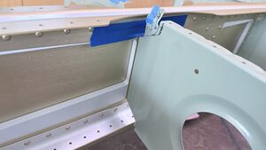
Incorrect tab 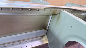
Material trimmed away
- The interfering material can be trimmed to allow clearance. Protect the main spar from accidental contact when trimming or grinding nearby material.
- In SECTION 33: Strut Attach Fittings the AN5 bolt can be a SUPER tight fit through the spar — recommended to check fit before skin assembly.


Page 31-19 (R0)
- Diagram shows wiring passing through a hole in the light assembly but no instruction exists and both harness legs already have connectors
- Landing-light harness (4-pin Series 1): Most likely this connector is cut off to direct wire to the Flyleds landing light. If wanting to connect via a plug, the harness end is a 206060-1 female plug; it needs a 4-pin male receptacle such as 206153-1, available as free-standing, flange-mount or board-mount. Source. See SECTION 05: General Information for more information on the CPC connectors.
- The bushing for the wire (most likely BUSHING SB375-4) does not seem to be supplied with the wing kit. It will most likely be supplied with a future kit.
Page 31-21 (R0)
- Outboard leading edge — tight holes. There may be holes that are not exactly in alignment, specifically with the leading edges. Recommend aligning before any reaming.
- Technique: Cleco every other hole, then wobble a pointed worn #30 bit in a handle, lever with two 1/8" scribes, or walk it with a bullet punch. Careful, the outboard skin is only .020. Source #1 - Source #2
- Set each rivet before pulling the neighboring cleco. Never force a pull rivet.
- Check nose-rib fluting before assembly; the factory spar splice plate flange contributes.